A segment that walks out of line during a storm rarely fails where it was made. It fails because of something that happened in the workshop: a mounting face that was not cleaned, a row tightened from one end until it was straight, or a set of fasteners torqued for the third season. The symptom appears on the route; the cause is in the fitting.
This procedure sets out the checks that matter at each stage of a joma blade installation, what each check proves, and what a failure looks like while it is still cheap to correct.
Joma blade installation: pre-installation inspection
Inspect the mount before the new segments are unwrapped, because the mount decides how the row will sit.
Start with the mounting face. It has to be flat, free of scale, paint build-up and corrosion, and clear of the debris that collects behind a blade over a season. A face that is not clean produces a segment that appears tight and is in fact supported at two points, which is how a row aligns in the workshop and misaligns after an hour on the road.
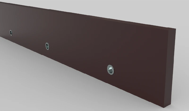
Then inspect the interface itself. Holes should be round rather than elongated, the mounting bar or clamp should be straight, and the hardware should be sound enough to develop the preload it was designed for. Where a hole has opened up, the new segment will move no matter how carefully it is torqued, and the mount becomes the item to repair. Confirm the segments on the bench against the order: length, thickness, insert pattern and hole spacing all have to match the drawing before anything is fitted.
Pass or fail is decided by measurement rather than by appearance. A straightedge across the mounting face, a check that the holes are round, and a note of any distortion are enough to decide whether to proceed.
Lifting and handling rubber segments
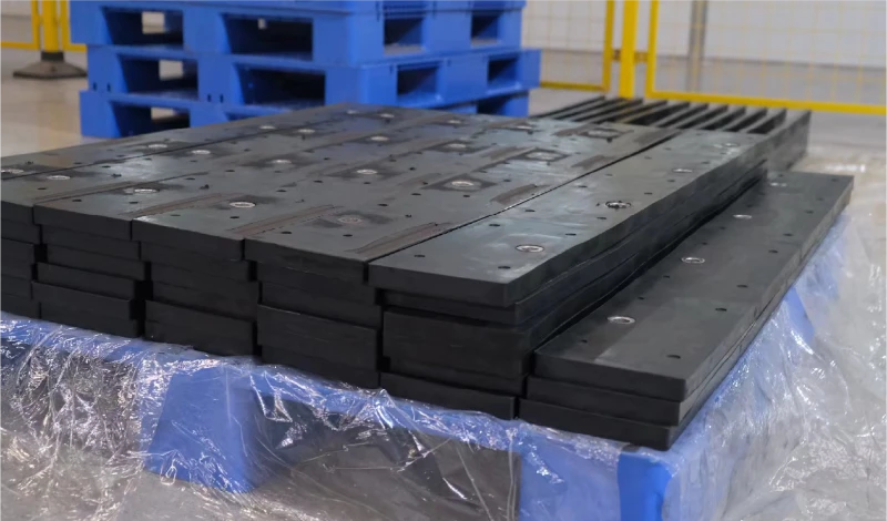
Handling is where a segment is most often damaged before it ever works. Support the segment along its length, never by a single end and never by the insert row, because the flexible base takes a set when it is bent and a base that has taken a set does not sit flat against the mounting face.
Cold conditions make the point sharper. Rubber that has been standing in a cold yard is stiffer and less willing to conform, so a segment forced into position on a frosty morning is more likely to be seated badly than one fitted in a heated shop. If the segments have been stored cold, bring them in before fitting rather than forcing them.
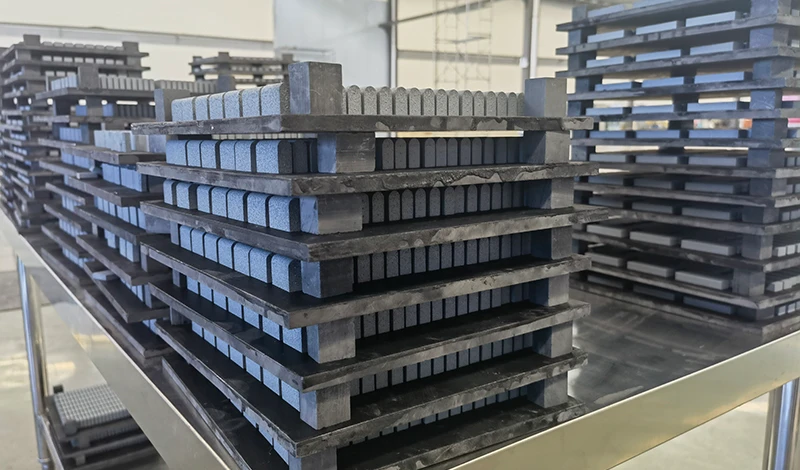
Two further habits are worth building into the procedure. Store segments flat and supported, not leaning against a wall, and keep the insert row clear of contact with the ground or the bench, because the wear face is the part that has to be flat when it goes on. The damage done in handling is rarely visible, which is why it shows up later as a joint gap or a proud segment rather than as a broken part.
Alignment along the moldboard
Alignment is a dry-fit exercise. Lay the row out before final tightening, starting from one end and working across, and confirm that the segment ends meet without a step and that the cutting line is continuous. Fit every fastener finger-tight first so the row can still be moved.
Check the line with a straightedge rather than by eye. A step of a few millimetres between two segments is visible on a workshop floor and invisible from the cab, and it changes the wear pattern across the rest of the row: the leading segment takes the impact and the trailing one takes the abrasion. Check the end overhang at both ends of the blade as well, since a row that is shifted to one side loads the outer segment harder.
Where the row includes mixed lengths, alignment matters more rather than less, because the step falls at a joint and a mixed row has fewer chances to average it out. Ordering to match an existing pattern is covered in JOMA style replacement blades; the fitting rule here is simply that the straightedge check comes before torque, not after.
Fastener sequence and torque
Bring the row up evenly, then torque to the value in the fitting instructions. Torque figures are specific to the fastener grade, the thread condition and the joint design, so they belong to the drawing that came with the system rather than to a general rule; the standards behind fastener grading and tightening practice are published by SAE International, and the dimensional and hardness testing that supports the components is maintained by ASTM International.
Sequence matters for the same reason it matters on any clamped joint. Working from one end loads the first segment fully while its neighbour is still free, which pulls the row out of line and can hold the second segment off the mounting face. Bring all fasteners to a light uniform load, confirm alignment, then apply final torque in the order specified, using a calibrated wrench and new fasteners of the correct grade.
Then come back to it. A clamped joint settles as the plates bed in, so the row should be re-checked after the first working shift. The wider torque and hardware routine, including the wear plates that share the same fasteners, is set out in the guide to blade hardware torque and wear plates.
Checking joint gaps
Joint gaps are the fastest indication of whether a row has seated correctly. Check them with a rule or feeler gauge after torque and note whether the gap is consistent along the row. A tight, even joint is the target; a gap that opens and closes suggests one segment is not flat against the mounting face.
The reason to take this seriously is what happens next. An open joint collects grit and water, and both ends of the two segments around it wear faster than the middle of the row, because each end is unsupported on one side. That wear appears as a step long before the inserts are consumed, which turns a row that should have been replaced at its wear limit into a row that has to be replaced early.
Gaps also carry information about the mount. If a joint will not close even with the fasteners at torque, the mounting face or the clamp is not flat, and the correct action is to correct the mount rather than to force the segment into place.
Post-installation road test
Run a short pass on a representative surface and then inspect the machine, while the evidence is fresh and the workshop is still available. A test pass takes minutes and it is the only check that loads the row in the direction it will actually work.
After the pass, look at four things: fastener torque across the row, the cutting line against a straightedge, the joint gaps, and the condition of the insert row for signs that a segment has been working at a different depth from its neighbours. Any adjustment made at this point is a workshop job; the same adjustment discovered in February is a roadside one.
Record the outcome with the machine, including the date, the segment identification and the torque applied. That record is what makes the next replacement a comparison rather than a fresh guess, and it is the same traceability principle applied at the point of fitting as the one used in production, described in the site’s quality control framework.
Common installation errors
Most installation failures fall into a short list, and every item on it is preventable without special equipment. Reading the list before starting is faster than diagnosing the result afterwards.
- Fitting onto a mounting face that was not cleaned or checked for distortion.
- Reusing fasteners that have already been torqued and worked under load.
- Tightening one segment fully before the row is aligned.
- Lifting or storing segments in a way that bends the flexible base.
- Mixing lengths or thicknesses without re-checking the cutting line.
- Skipping the re-torque after the first working shift.
- Accepting a joint gap because the fasteners are already at torque.
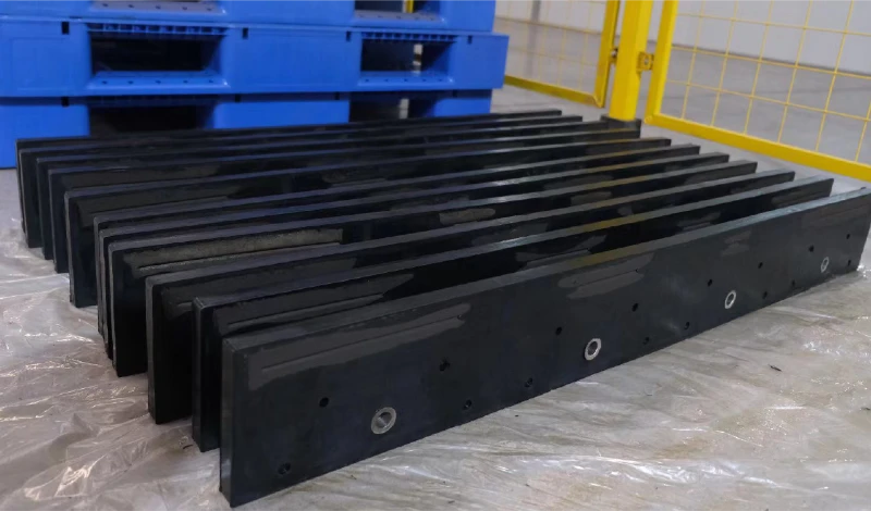
Installation practice on this scale sits inside a wider maintenance routine, and the operator-facing side of it is covered by the Snow and Ice Management Association, while the equipment context comes from the Association of Equipment Manufacturers and the research published by the Transportation Research Board.
The conclusion is that a segment row is a clamped assembly, and it behaves like one. Clean and measure the mount, handle the segments so they stay flat, align before torque, use new hardware to the specified value, check the joints, and re-check after the first shift. SENTHAI supplies replacement rubber-flex segments and carbide wear parts produced in Rayong, Thailand, with lot-level traceability across the production batches.
FAQ
Can the old fasteners be reused when fitting new segments?
Reuse is the most common cause of a row that loosens after the first shift. A fastener that has already been torqued and worked under vibration has lost some of its preload, and its threads and coating are no longer in the condition they were supplied in. Fit new fasteners of the specified grade with each segment and keep the retired set out of the spares bin.
Do segment fasteners have to be tightened in a sequence?
They do, and the reason is the seating rather than the hardware. Tightening one segment fully before its neighbour is aligned pulls the row out of line and can lift the second segment off the mounting face. Bring all fasteners up evenly, confirm the cutting line, and then apply the specified torque in the order given in the fitting instructions.
Does a small gap at a segment joint matter?
A uniform, tight joint is normal; a gap that varies along the row is not. Grit and water collect in an open joint, and the exposed ends of both segments wear faster than the rest of the row. Check the joints with a rule or feeler gauge after torque and again after the first shift, because a segment that has settled slightly will show up as an uneven gap.
When should a new segment row be re-checked after installation?
After the first working shift, while the machine is still in the yard. New fasteners settle as the plates bed in, and a small amount of preload loss is normal. Re-check the torque across the row, confirm the cutting line against a straightedge, and inspect the joints. Doing that once converts most installation faults into an adjustment on site instead of a failure on a route.
Send the machine model, the mounting measurements and the segment pattern you are fitting. The SENTHAI engineering desk will confirm the hardware set, supply the segments with matching fasteners, and provide the fitting data for the torque check.